Line-following Robot
Summary
A mobile robot designed to follow a line without any programming. The project focuses on how to use basic components for decision making instead of digital systems and code.
Context
Completed as part of an assignment for MTRX1701 at the University of Sydney. We didn’t design the circuit ourselves, because we had just been introduced to the engineering design process and weren’t familiar with how to implement components effectively. Instead the assignment went into great detail on how to tackle the problem and showed how the design process was used in each step. We also learnt how to design a printed circuit board (PCB) for our robot, which was ordered and used to teach us how to solder components to PCBs.
Technical breakdown
The robot works on the principal of how much light is reflected depending on the colour of the surface it hits.
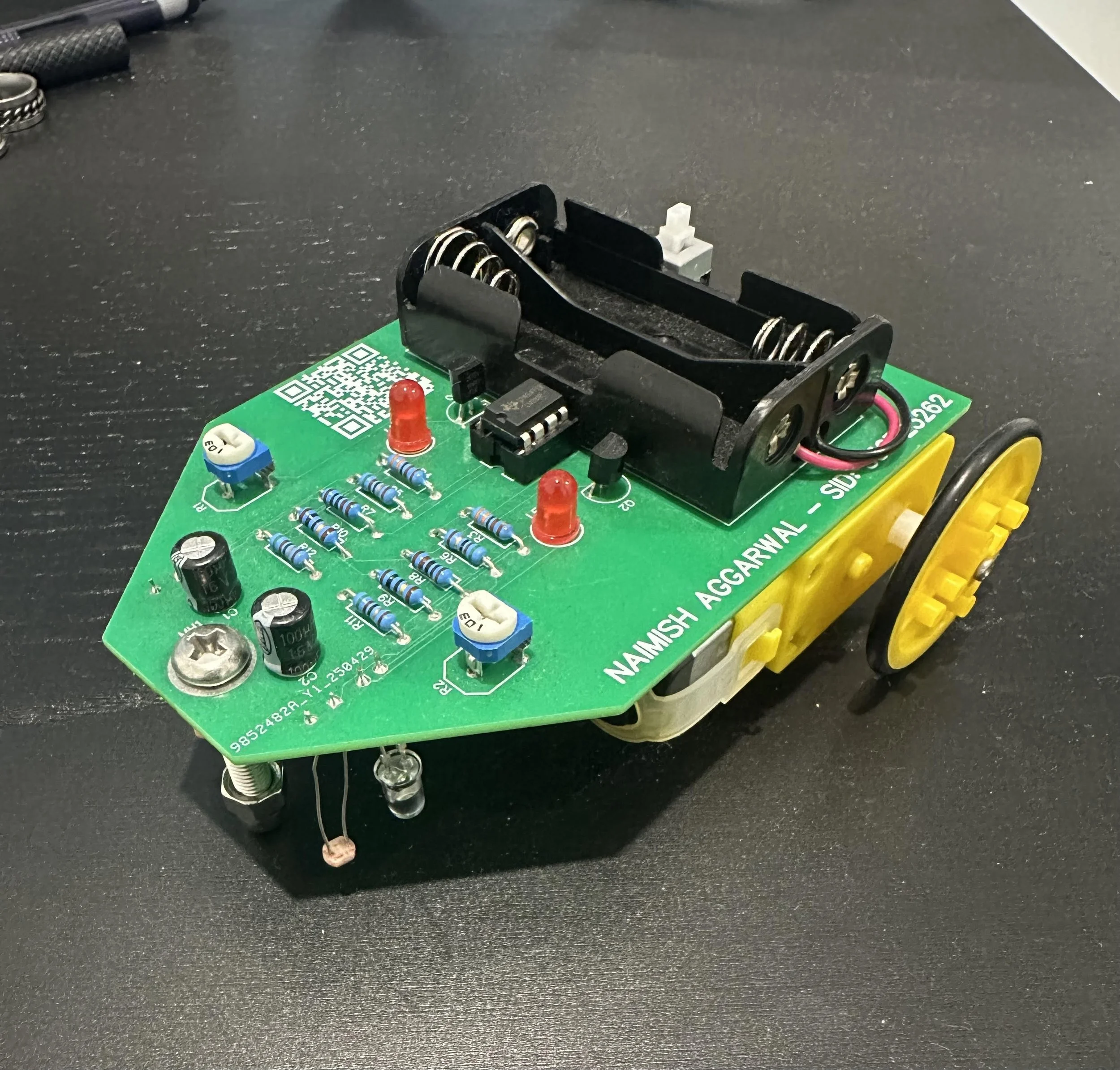
There are 2 LED-LDR pairs (left and right) used for a simple sensor circuit. The LED is used to shine light on the ground and the LDR is used to measure the intensity of light reflected. The LDR decreases its resistance with more light, and hence the voltage across it also decreases. Using this we can detect when the LDR is above the white page or the black printed line, since the white page will reflect more light, decreasing the resistance; and the black line will absorb more, increasing the resistance.
The voltage outputs from these 2 sensor circuits are compared to determine which way to move. If the left has a higher voltage, it is assumed the line is below the left sensor. To stay on the line the robot must then turn right, so only the right motor is turned on. The same principal is applied to the right sensor and left motor. When both sensors are at a similar voltage (either both above white or both above black), electrical noise will cause fluctuations and result in both motors being activated roughly the same amount, and the robot goes in a straight line. Combining all these behaviours together allows the robot to follow the line.
Video demonstration of the Line-following robot working.
Key Learnings
Firstly, I learnt how to use the V-model to solve a problem. It was much more useful to actually work through it than to just read about it and remember the steps. This comes up in later projects in Sem 2, where we aren’t just given a solution like this time, only a problem and a bunch of constraints. Learning how to implement the model really helps with breaking it down instead of getting overwhelmed.
Secondly, learning how to design a PCB was a very informative experience. Learning about the conventions when wiring, and trying to route lines without inducing short circuits was challenging to say the least. We also had to pay attention to the placement of specific components, like the LDR and LED in the sensor circuit had to be close together, otherwise the sensing wouldn’t be reliable. I now feel confident that I can design PCBs for future projects, both university related and personal
Finally, soldering the board together also taught me a lot. While I did have experience soldering some wires in high school, it was different to soldering components. We had to make sure the solder made a solid connection, but ensure we didn’t put so much that it became a big lump. It was useful to learn what to be careful of for future projects too.